How To Wire (or re-wire) a boat
I know what you’re thinking. “How is this lunatic going to cover such a complex topic as – how to wire a boat – in one post?“
Well – you’re right – We won’t be able to cover every situation, or every possible setup on every boat. And if all this info is new to you, you’re probably best hiring a professional marine electrician to do it for you (local install support directory). But, we’ll try anyway to explain some of the general theory and best practices in hopes it will help.
In this guide we’ll stick with the 12Vdc power distributions systems, as opposed to engine or gauge wiring.
A few notes before we start:
- Positive wires are red (in our guide, your boat may have other colors)
- Negative wires are black (or may be yellow on your boat)
- Current is measured in Amps (A)
- Potential difference is measured in Volts (V)
- Current flows through the wires (like water through a pipe). Too much current can heat up the wiring to the point of starting a fire
- Voltage does not “flow” it is a measurement of potential to do work. Like water pressure in a pipe
I’m in a hurry…
Products To Kick-Start Your Project


1. The Electrical Source: a Battery
In a boat, electricity is stored in one or more batteries. The batteries are charged by your engine’s alternator or auxiliary battery charger. They can hold an enormous amount of energy, capable of pushing hundreds, or even a thousand amps (more than your entire house uses)… so care must be taken, and proper circuit protection should not be ignored.
Greatly generalizing the topic here, but you usually run into two types of batteries in the size of boat we deal with:
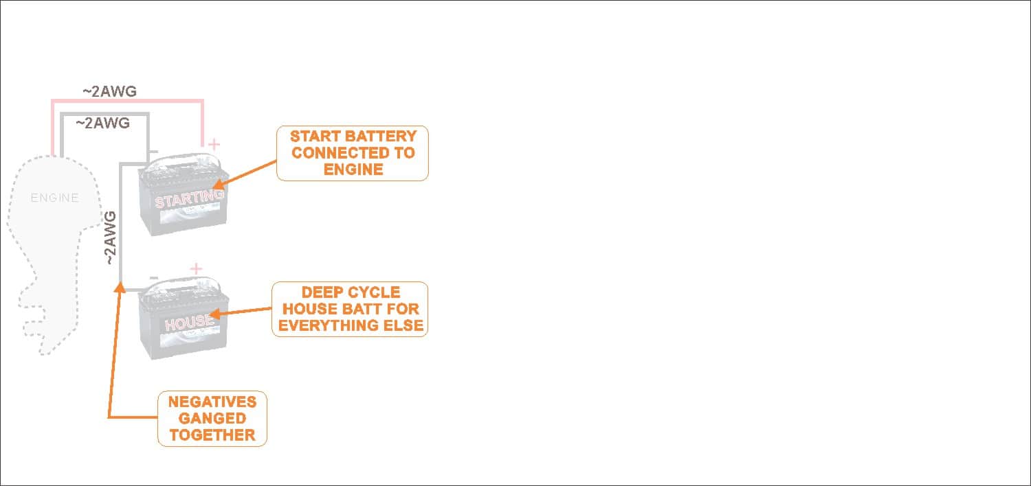
- Starting Battery – Has high current rush capacity
- Deep Cycle Battery – Capable of deep discharge without harm
The two setups we most often run into is:
- Single Engine – 1 starting, and 1 house battery
- Twin Engine – 2 starting, and 1 house battery
Every non-engine wire (EVERY ONE) should be circuit protected with a fuse or circuit breaker
Batteries have positive and negative. For current to flow (which does the work) a complete circuit must be made from positive back to the negative. Any break in the circuit anywhere will stop the load from operating (which you probably already know or you wouldn’t be reading this to try and fix your marine wiring issue).

A normal battery might be able to push 800A or more current
A normal battery might have 70-80AH (amp hours) of capacity. Meaning it can run a 1A load for 70 to 80 hours, or a 10A load for 7 to 8 hours before it is discharged.
So let’s get our boat wiring diagram started with our batteries!
TIP: (use the tabs to view and hide notes)


Testimonial:
“Thanks Rob… I know you’re super busy – and this ain’t the biggest project in your shop, I’m sure. But the level of service I’ve gotten so far is five-star. Much appreciated. Have an awesome holiday!”
-Rick K. Angels Camp, CA
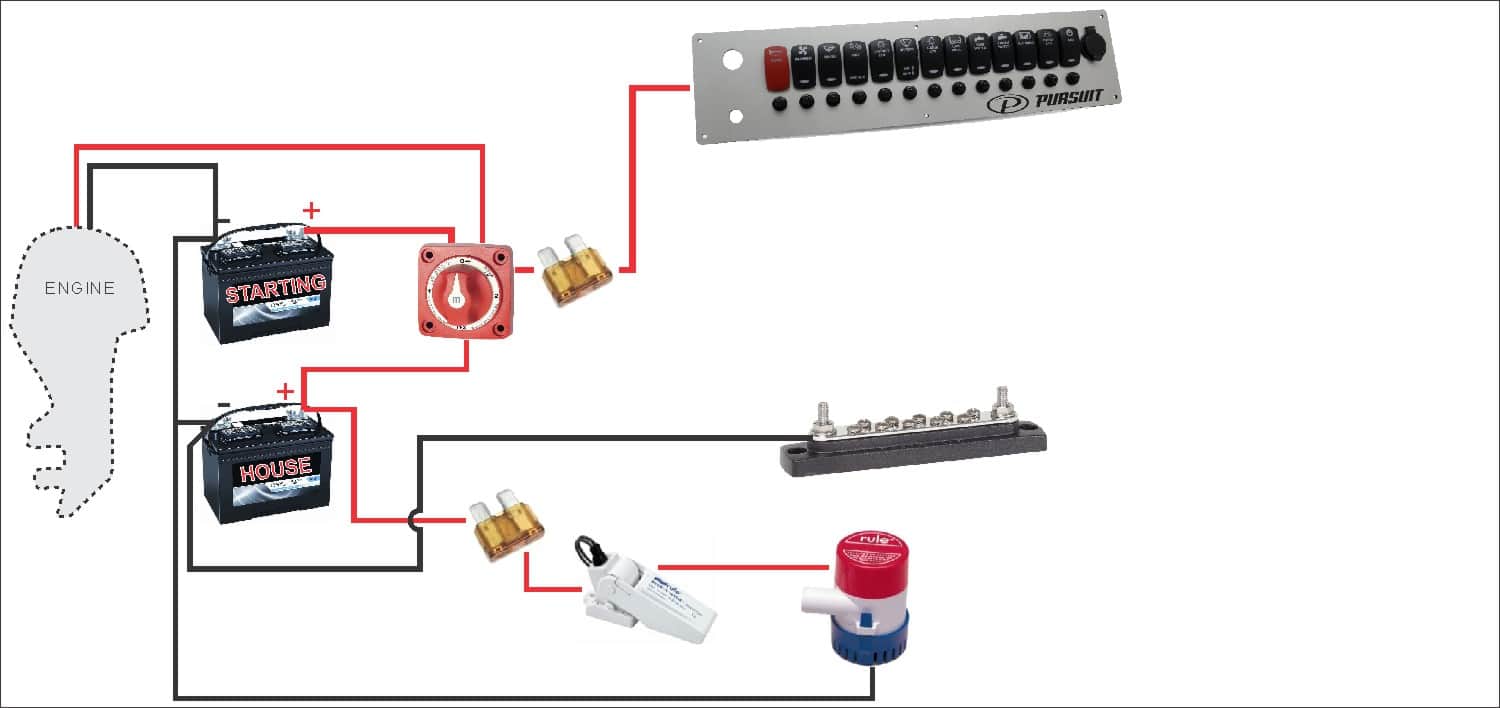
2. Main Battery Switch
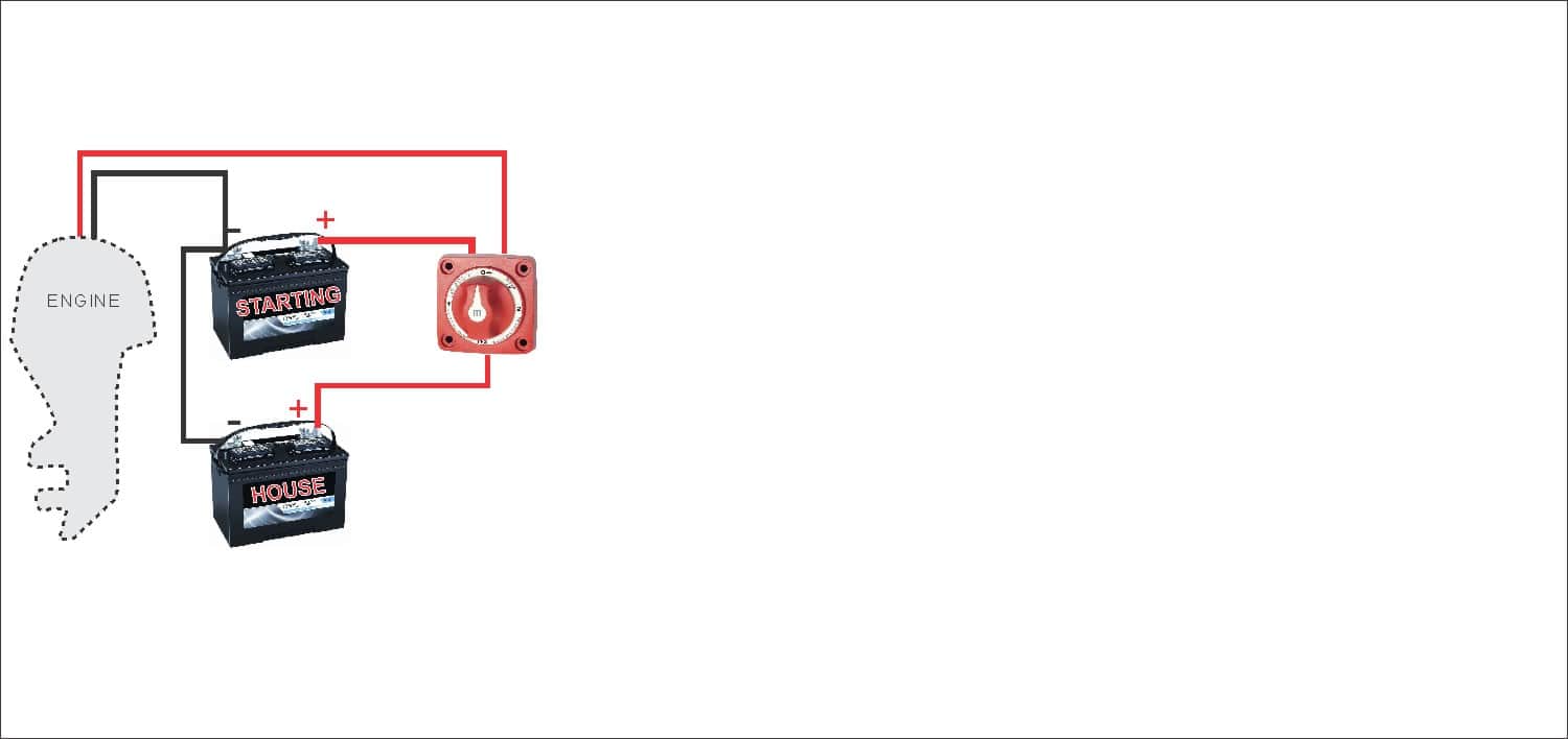
In nearly all cases your boat wiring system should have a marine-grade main battery disconnect switch. This allows you to open the switch turning everything off at once. In this case, We’ve shown a 1-2-BOTH type battery switch.
Both battery positives are running through this switch, and you can use it to select which battery you want to output, similar to an A-B switch. But a 1-2-BOTH marine battery switch also allows you to parallel both batteries. Both settings might be used when you are running your engine and want to charge both batteries from the alternator, or if you need to parallel the batteries in an emergency to help start your engine if your start battery becomes too depleted.
Remember to turn your battery switch to the “house circuit” when your engine is not running, so you are only drawing down your deep cycle house battery meant for that purpose.
we’ve changed the diagram a bit now to show the start battery running through our new marine battery switch
A Double Pole ON/OFF/COMBINE battery switch (like this one) is a great choice for a single-engine, two battery boat wiring system. It allows your house and starts battery to remain isolated except for emergency conditions.

Used to shutoff everything and prevent trickle charges from draining your battery


3. Battery Switch Bypass Loads (Bilge Pump, etc)
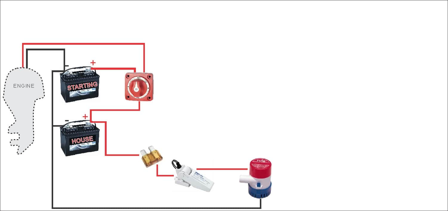
It’s pretty standard in boat wiring to bypass the main battery switch for one thing: The boat’s bilge pump float switch. This way, even if your battery switch is off, if your boat starts filling with water the pump will still kick on. I’d rather have a dead battery than a swamped boat.
Notice the fuse shown – this needs to be circuit protected with an inline fuse like this one. I’m also showing the negative return wiring for the bilge pump in this step.
A stereo memory line might be another “bypassed” load
We have an in depth article here on how to wire a bilge pump… check that out as well for more details.

You’ll probably want to bypass your battery switch for this important load

Testimonial:
“I have been thrilled with my new panel with a 3 foot harness. It looks great and using your tutorials I have been able to rewire my 10 year old center console. The support I received from New Wire Marine went above and beyond. Thank You!”
-Robert B. Bethesda, MD.

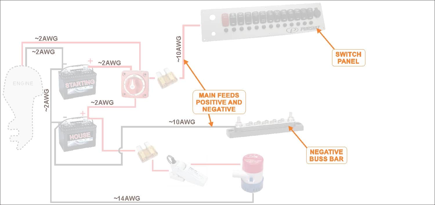
4. Get the Source to the Boat’s Helm
The next step is to get the power from the house battery up to the switch panel where we can use it to do some good. Two conductors – a positive from the battery switch (with a fuse) and a negative from the ganged together battery negatives should be ran to where the central switch panel is. You should use marine grade primary wire for this.
This is sometimes a long wiring run on a boat. Plus these two conductors will carry the current of all your electrical loads combined, so they are typically fairly beefy cables. Even a small boat (3-5 loads) we’d recommend at least 12AWG wire for this. 10AWG for larger boats (5-10 loads) is normal. 8AWG is getting toward over-kill in most cases for boats under 30ft.
Remember these are all generalities, there are many valid reasons to make exceptions
Keep in mind that the longer your wiring run from the battery to switch panel is, the more voltage drop you’ll have (more about voltage drop). Prevent voltage drop by using larger cable.
The power cables will be run to your New Wire Marine custom marine switch panel and your tinned marine negative bus bar. Most of our switch panels include waterproof resettable circuit breakers with all the connections pre-made to make them work, that’s how it is shown here.
Note, if you do not order circuit breakers in your boat switch panel you’d need to insert a fuse block before the panel, then individual conductors from each fuse to each panel (we really recommend including circuit breakers in your panel if you have space, it will really make your life easier installing and maintaining your new custom switch panel).
The main house battery positive conductor will feed directly into the new switch panel. The main battery negative should go to a negative buss bar (like this one), where all your boat’s load negatives will eventually be attached.

Example of one of our Switch Panels with Built in Circuit Breakers
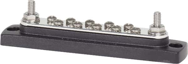
Example negative bus bar. Note, this is different than a terminal block – all the screws are “bused” together.

Testimonial:
“Excellent company and personnel! They asked the right questions and provided great solutions!”
-Tre McC. Houston, TX
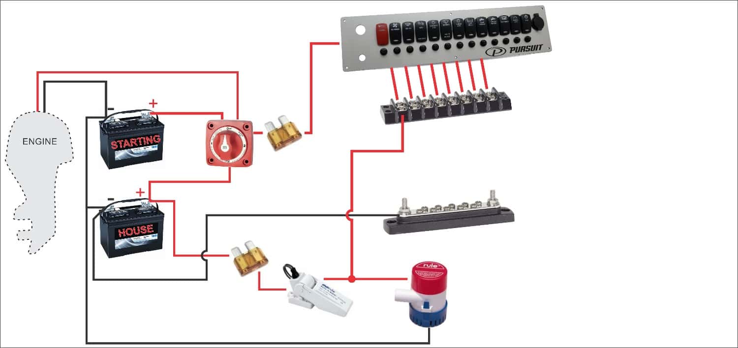
5. Install Terminal Block as Breakout Point
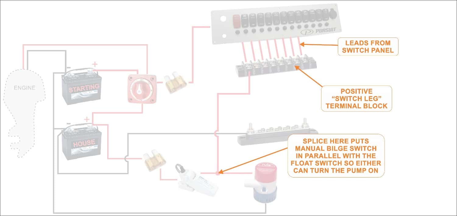
If you get your boat’s switch panel fully wired (more on that here), then you’ll have an easy to install wiring harness coming off pre-installed with heat shrink labels, and ring terminals. This is meant to land on a terminal block like this one.
Each switch output gets its own gang on the terminal block, and with the labels right there it makes a handy breakout point for troubleshooting or adding items down the road. These are the positives of course – the “switch legs” – and all that’s needed is to crimp a #8 ring terminal on the positive load wiring that runs out around your boat to the various loads.
We’re showing one output from the terminal block here for the manual bilge pump switch. It’s shown in parallel with the float switch, so either switch can turn the pump on (read more about bilge pump wiring here).

(click to enlarge)
This is how one of our fully wired switch panels would interface with a terminal block. With our heat shrink labels it’s easy to hook up your load wiring and troubleshoot.
Testimonial:
“I have enjoyed working with the entire team, they have been super, just a great company to do business with.”
-Jim R. Vero Beach, FL

6. Run Load Wiring to the Terminal Block and Buss Bar
From here the rest of the wiring is straightforward. Just hookup your existing boat wiring infrastructure to the terminal block and buss bar. Positives to the terminal block, and negative to the bus bar.
Most are terminated with standard #8 ring terminals. The positives of course must be installed on the correct gang associated with the respective switch for that load. The negatives can go on any screw on the buss bar, they are just trying to get back to the negative post on the battery.

From here on our it’s just a + and – wire run to each load
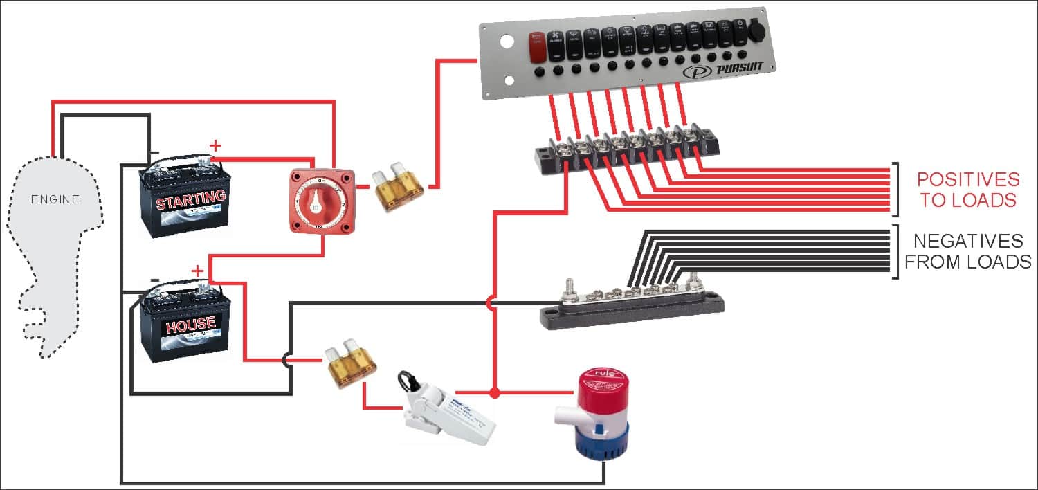

Here is a tabbed step-by-step diagram for how to wire a boat
Dig our Boat Wiring Content?
We’ve got lots more cool boat wiring stuff to share!
Signup below for the occasional interesting – not spammy – Boat Wiring tip email, and we’ll email you our complete
13-Page PDF with a bunch of schematics, tips, tricks and checklists to help with your re-wire project, and beyond!
