

VJD2 rocker switch wiring
How to Wire a 10-Terminal Rocker Switch
By New Wire Marine Technical Team · Updated October 5, 2026
Ten terminals look like a lot until you sort them into two groups.
On this Carling VJD2 ON-OFF-ON switch, six terminals run the two switched circuits. The other four power two independent lamps. That split is what lets a NAV/ANC switch work with a separate panel-backlight circuit.
Before you move a wire, confirm the switch body and open the diagram for the backlight setup you want. That one check helps keep the navigation lights, anchor light, and switch illumination working in the right positions.
Watch the explanation
Pam explains the VJD2 10-terminal switch
This 18:58 video walks through the switch body, the ten terminals, and the two common ways to wire NAV/ANC backlighting. Use the terminal map and wiring guide below when you are ready to make the connections.
Before you connect a wire
What the ten terminals do
The VJD2 is a double-pole, double-throw ON-OFF-ON switch. Terminals 1–3 form one switched circuit and terminals 4–6 form the second. Terminals 7–10 are reserved for the two independent lamps.
- 1: circuit 1 output with the switch down
- 2: circuit 1 positive input
- 3: circuit 1 output with the switch up
- 4: circuit 2 output with the switch down
- 5: circuit 2 positive input
- 6: circuit 2 output with the switch up
- 7 and 9: lamp negative returns
- 8: top-lamp positive trigger
- 10: bottom-lamp positive trigger
Orientation matters: read the terminal numbers from the back of the switch exactly as shown in the diagram. Do not mirror the layout from the front.

Wire the switch one group at a time
The jumpers change depending on how you want the switch lamps and the rest of the panel backlights to behave. Work through these steps first, then follow the matching New Wire Marine diagram for the actual connections.
Step 1
Confirm the switch and the result you need
Verify that the body is a VJD2 ON-OFF-ON switch with two independent lamps. For the NAV/ANC application in the current guide, the up position powers the navigation and anchor-light loads, the center position is off, and the down position powers only the anchor-light load.
Step 2
Disconnect power, photograph, and label
Turn off the battery connection feeding the panel and verify the circuit is de-energized. Photograph the rear of the existing switch and label each wire by circuit and terminal before removing it. If the old and new bodies do not match, stop and resolve the difference before transferring wires.
Step 3
Orient the terminal numbers from the back
Place the switch beside the terminal map in the same orientation. Separate terminals 1–6, which carry switched load current, from terminals 7–10, which serve the two lamps. This prevents a lamp terminal from being mistaken for a load connection.
Step 4
Choose how the backlights will be triggered
Decide whether the NAV output should also trigger the panel’s backlight bus or whether a separate panel-light or dimmer circuit will power the switch’s top lamp. Those arrangements do not use the same external connections, so choose the matching page in the current wiring guide before installing jumpers.
Step 5
Connect the protected feed and the two loads
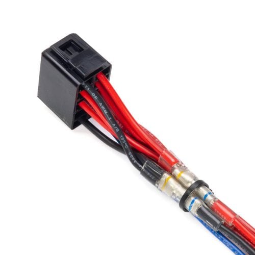
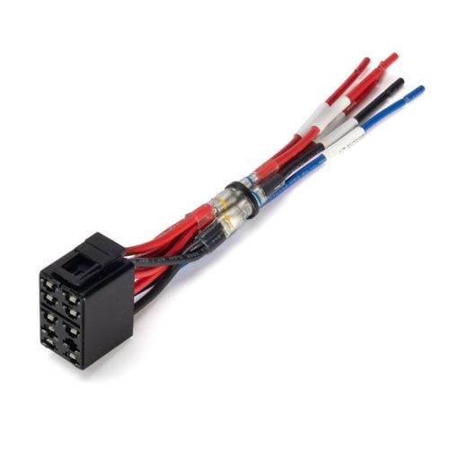
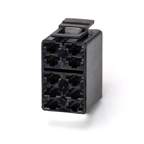
Use the selected diagram to connect the appropriately protected positive feed, the navigation-light output, and the anchor-light output. Install only the jumpers shown for that configuration. A connector housing, terminal block, or pre-wired harness can move crowded connections away from the switch body and make later service easier.
Step 6
Complete the lamp circuits
Connect the lamp positives and negative returns exactly as shown for the chosen backlight arrangement. Keep the lamp wiring distinct from the two switched-load circuits. Before restoring power, tug-test every terminal and confirm that no jumper or connector can contact an adjacent terminal.
Step 7
Restore power and test every position
Restore power only after the connections are secure. Check the up, center, and down positions, then verify the top and bottom lamp behavior and any connected panel backlights. Disconnect power again before correcting an unexpected result.
Choose the backlight arrangement before adding jumpers
The ten-terminal body is useful because both lamps can be powered independently. The New Wire Marine 10-Terminal NAV/ANC Wiring Guide shows two ways to control the panel backlights. Choose the one that matches how your panel is supposed to work.
Keep the verified wiring guide open while you work
The five-page guide shows the terminal map and both backlight arrangements for the Carling VJD2 10-terminal switch with two independent lamps. Keep the matching diagram beside you while you orient the switch and make the connections.
Products for this project
Choose the switch and wiring approach that fit the panel
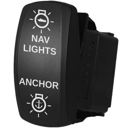
The complete NAV/ANC switch provides the labeled actuator and compatible body. The WirePack is a pre-wired NAV/ANC option, while the connector housing supports a custom harness. A multimeter helps verify the circuit is de-energized and check results when used correctly.
Confirm switch-body compatibility, lamp voltage and color, circuit protection, wire size, terminal type, and the selected diagram before ordering or connecting parts.


Frequently asked questions
Are all 10-terminal rocker switches wired the same way?
No. This guide covers the Carling VJD2 ON-OFF-ON body with two independent lamps. Confirm the exact body part number, circuit, lamp type, voltage, and manufacturer diagram before making connections.
Why does the VJD2 need ten terminals?
Six terminals serve the two switched circuits and four serve the two independent lamps. The lamp circuits can therefore be triggered separately from the load contacts.
Why is this switch commonly used for NAV/ANC lights?
Its ON-OFF-ON, double-pole arrangement can be configured so the up position powers the navigation and anchor lights while the down position powers only the anchor light. The independent lamps also support more flexible panel-backlight control.
Can I replace a 7-terminal NAV/ANC switch with this 10-terminal body?
Not by moving wires terminal for terminal. The lamp behavior and external connections differ. First determine how the existing switch and panel backlights are wired, then use the diagram for the replacement body and desired backlight arrangement.
Do all the jumpers have to fit directly on the switch?
No. The current New Wire Marine guide notes that a terminal block or connector can move some junctions away from the crowded switch body. The electrical connections still need to match the selected diagram.
When should I stop and call a marine electrician?
Get qualified help when the switch body or existing wiring cannot be positively identified, conductors or terminals are damaged, circuit protection is unclear, or the required testing and repair are outside your experience.
Related guides and source information
Rocker Switch Wiring Diagrams
Compare VJD2 and other Carling-style switch bodies before selecting a wiring diagram.
Choosing the Right ON-OFF-ON Switch for NAV/ANC
Understand the practical differences among 7-, 8-, and 10-terminal NAV/ANC switch bodies.
How to Wire a Boat
Review circuit protection, wire sizing, connections, and the complete path from the power source to the load and back.
Carling V-Series Contura II and III specifications
See the manufacturer’s switch-family specifications and terminal arrangement resources.