
ON-OFF at the helm
The switch controls manual operation. The automatic float-switch feed remains independent, so it cannot be disabled at the helm.

Bilge pump and float-switch wiring
The way you wire the helm switch determines whether the float switch can still start the bilge pump when nobody is aboard.
When wiring a bilge pump with a float switch, you still need manual control at the helm. A simple ON-OFF switch can control the manual feed while a separate fused feed keeps the float switch available. A MAN-OFF-AUTO switch puts both modes at the helm, but its OFF position can also shut down automatic operation.
The diagrams below compare those two arrangements for a common two-wire pump with a separate float switch, so you can choose the one that fits the boat. There is also a practical option for making the pump easier to disconnect when it eventually needs service.
The quick answer
New Wire Marine normally recommends using the helm’s ON-OFF switch for manual control. A separate fused positive feed runs through the float switch. Both feeds connect to the pump, so either switch can turn it on.
The switch controls manual operation. The automatic float-switch feed remains independent, so it cannot be disabled at the helm.
The switch selects manual or automatic operation. In the arrangement shown below, the center OFF position also shuts off the automatic path.
Before you move a wire
Do not assume that turning off the main battery switch killed power to the pump. The automatic feed may stay live while the rest of the boat is off. Remove its fuse or disconnect it at the source, then verify that the circuit is dead before handling a terminal.
Use the fuse size, wire size, and connection method specified for your pump and float switch. These diagrams explain how the controls work together; the instructions supplied with the equipment provide the installation details.
Choose the control arrangement
Look at what happens when the helm switch is turned off. That is the important difference between these two circuits.
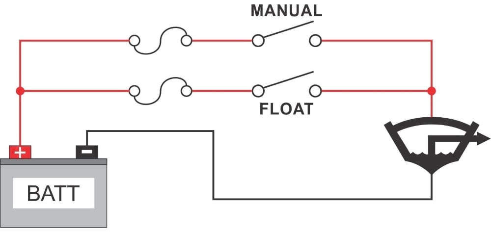
For a two-wire pump with a separate float switch, the manual and automatic feeds connect in parallel at the pump. Turning the helm switch off stops manual operation but leaves the fused float-switch path available.
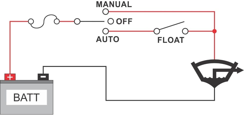
The helm switch selects the manual feed or the float-controlled feed. With this circuit, moving the rocker to OFF stops both paths, so the float switch cannot start the pump.
Step 1
Start with the model number and the wire labels on the pump. The diagrams on this page cover a two-wire pump with a separate float switch. If your pump has separate automatic, manual, and negative leads, it is a different three-wire setup. Use the diagram supplied for that model.
Source note: Current Rule/Xylem instructions use different diagrams for standard two-wire pumps and automatic three-wire pumps. Check the instructions for the exact pump before assigning any wire by color or function.
Step 2
Positive power runs through the specified fuse, then through the float switch, before reaching the pump. When rising water lifts the float, the switch closes and completes that path.
With the recommended ON-OFF arrangement, this feed does not pass through the helm switch.
Step 3
Run the manual positive feed from its protected source, through the helm switch, and back to the pump’s positive connection. It joins the float-switch feed there. Turning on the helm switch bypasses the float switch and runs the pump.

Step 4
Connect the pump’s negative lead to the boat’s negative return using the wire size and connection method required for the pump and the full circuit length.
Step 5
Restore power and run the pump from the helm. Then return the helm switch to its normal position and test the float switch using the method in its instructions. Each control needs to start the pump. If one does not, disconnect power and trace that side of the circuit before replacing anything.
If the pump does not run
Start with the automatic feed, its fuse, the float switch, and the connection where that path joins the pump.
Check the helm switch, its protected positive feed, and the manual wire running back to the pump.
Confirm battery power, circuit protection, the shared pump connection, the negative return, and the pump itself.
The wiring may be fine. Check the pump inlet, discharge hose, outlet, and installation against the pump manufacturer’s instructions.
Make the next replacement easier
A Deutsch-compatible connector gives you a clean place to unplug the pump. When the pump needs service, you can remove it without cutting the finished harness.
The connector still has to fit the job. Match the housing, contacts, seals, wire size, and current rating to the installation, and mount it where you can reach and inspect it.
The Living for Sail video shows this connector style being assembled and used on a boat project.
Use the terminal-specific diagram for that switch body. Do not transfer terminal numbers from a different rocker-switch layout.
Parts for this project
The two rocker switches below are alternatives, not a pair. Match the switch, cable, float switch, and circuit protection to the equipment in the boat and to the manufacturers’ instructions.

Controls the manual feed while the automatic float-switch path remains independent.

Selects manual or float-controlled operation when the circuit is built for this arrangement.

Closes the automatic feed when rising bilge water lifts the switch.

Provides three conductors for common manual, automatic, and negative bilge-pump runs when the specified wire size is appropriate.
Planning a removable pump connection? Browse Deutsch-compatible connectors and confirm that the selected components fit the wire and circuit.
With the independent automatic feed shown in the ON-OFF diagram, yes. The float-switch path does not pass through the helm switch. A MAN-OFF-AUTO arrangement behaves differently because the center OFF position can interrupt automatic operation.
Not without checking the pump instructions. Many automatic pumps use three leads for automatic power, manual override, and negative. Follow the diagram supplied for the exact pump model.
Use the pump and float-switch manufacturers’ specifications, then account for the full circuit length. There is no single fuse or wire size that fits every pump.
In the illustrated circuit, voltage from the closed float-switch path reaches the switch’s indicator connection. That lets the rocker show that the pump is running even though the manual switch was not turned on.
No. It is a serviceability choice. When the connector is correctly selected and assembled, it can make pump replacement easier without cutting the harness.
