

Three-terminal marine rocker-switch wiring
How to Wire an ON-OFF SPST Rocker Switch
By New Wire Marine Technical Team Updated October 6, 2026
This is one of the most common ON-OFF switches found on a boat. It controls one accessory, and the light in the rocker comes on when that accessory is running.
There are only three connections to make. Terminal 2 brings power into the switch, terminal 3 sends power to the accessory, and terminal 7 provides the negative connection for the light in the rocker.
Once those three wires are in the right place, the switch and its indicator work together. You also have a circuit that’s much easier to understand the next time you’re behind the panel.
Watch the wiring
See the V1D1-B60B connected and tested
In the video, we point out each terminal, wire a simple 12V test circuit, and show how the light in the rocker works with the accessory.
How to wire the three-terminal SPST switch
Step 1
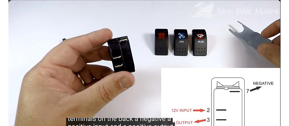
Find terminals 2, 3, and 7
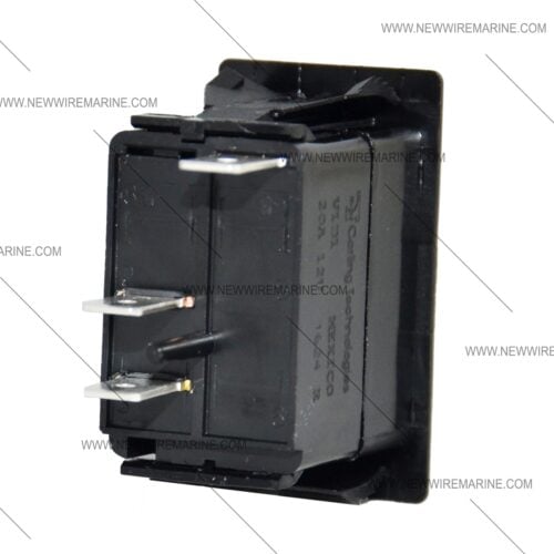
Look for the numbers molded into the back of the switch. Terminal 2 is power in. Terminal 3 is power out to the accessory. Terminal 7 is the negative connection for the light in the rocker.
Step 2
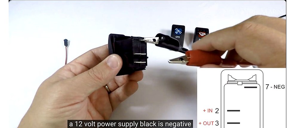
Connect negative to 7 and 12V power to 2
Connect the negative return to terminal 7. Then connect the protected positive feed to terminal 2. Push each quick-connect terminal all the way onto the switch tab, and leave enough slack so the wire isn’t tugging on the connection.
Step 3
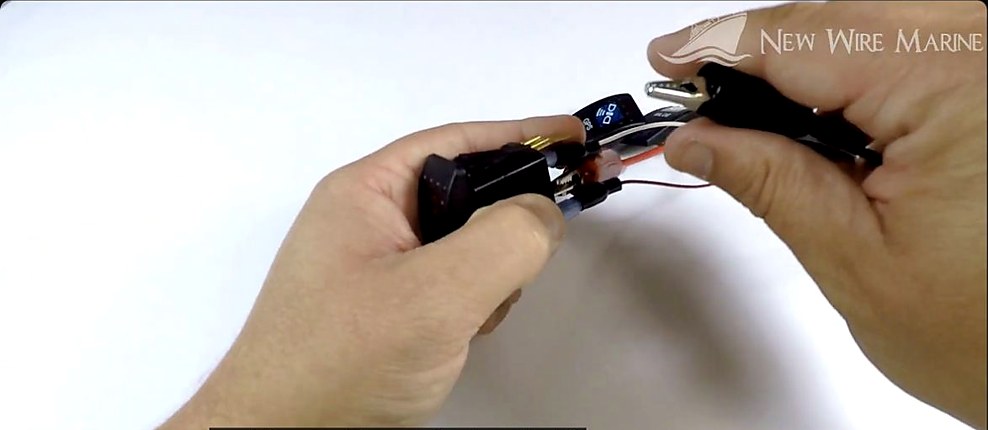
Connect the accessory to terminal 3
Terminal 3 sends power out when the switch is ON. Connect it to the positive wire for the light, pump, or other accessory you’re controlling. The accessory’s negative wire goes back to the boat’s negative circuit, not to terminal 3.
Step 4
Restore power and test the switch
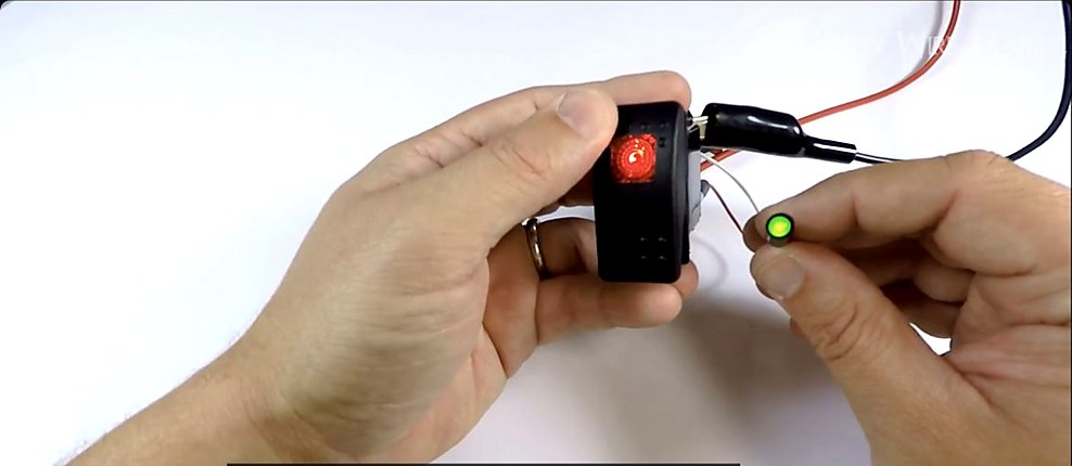
Check the connections one more time, then restore power. Turn the rocker ON. The accessory should run and the light in the switch should come on. Turn it OFF and both should go dark. If the accessory works but the rocker stays dark, disconnect power and recheck terminal 7.
Before ordering a replacement
Check the switch body and terminal count
Use this guide for
A three-terminal V1D1-B60B, or a compatible V1D1/V1DA ON-OFF switch, with one light that comes on only when the switch is ON.
You’ll need a different diagram for
A four-terminal switch with a separate backlight and indicator, an ON-OFF-ON switch, or a momentary switch. They don’t use the same terminal layout.
Working with a different rocker switch?
Find the part number on the switch body and count the terminals before you choose a wiring diagram.
Products for this project
The switch and connections shown in this guide
Start with the right switch body, then match the terminals and wire to the circuit already in the boat. Add a label while you’re there. The next person who opens the panel will know what they’re looking at.


Frequently asked questions
What does SPST mean?
Single Pole Single Throw. In plain English, one switch controls one circuit, and the switch has two positions: ON and OFF.
Why does the switch need a negative connection?
Terminals 2 and 3 handle positive power for the accessory. Terminal 7 gives the light inside the rocker the negative connection it needs to work.
What is a dependent lamp?
It’s a light that follows the switch. Turn the rocker ON and the light comes on. Turn it OFF and the light goes out.
Can this replace a four-terminal illuminated switch?
Not if the four-terminal switch has a separate backlight and indicator. Check the body marking, terminal count, and lamp setup before you order a replacement.
What if the accessory works but the rocker stays dark?
Disconnect power and check terminal 7 and the negative return. If both connections are good, confirm that you have the correct three-terminal switch body before moving any other wires.
Keep learning
Rocker Switch Wiring Diagrams
Match the body number and terminal count to the correct circuit.
How to Wire a Boat
See how the switch fits into the complete protected 12V circuit.