Separate electric actuators
Each tab has its own electric actuator. The rocker switch changes the polarity sent to the actuator motor so it can extend or retract.

Trim tab switch wiring
Your trim tab switch may say the same thing on the front whether the boat has electric actuators or a hydraulic pump. The wiring behind it is not the same.
Electric tabs move by reversing polarity at each actuator motor. Hydraulic tabs use one pump and separate valves to move the port and starboard tabs. Start by identifying the system on your boat, then follow the diagram and video for that system.
These diagrams show two common ways to wire momentary rocker switches for electric and hydraulic trim tabs. Use them as switch-wiring references, and follow the trim tab manufacturer’s instructions for the actuators, pump, circuit protection, and any system-specific requirements.
The quick answer
Both systems use momentary (ON)-OFF-(ON) rocker switches, so the switch returns to center when you let go. On an electric system, the switch reverses positive and negative to change actuator direction. On a hydraulic system, the switch pairs pump direction with the port or starboard valve.
Choose your system
Each tab has its own electric actuator. The rocker switch changes the polarity sent to the actuator motor so it can extend or retract.
A hydraulic power unit supplies pressure and retract functions. Separate port and starboard valve wires decide which tab moves.
Before you move a wire
Turn off and isolate the boat’s battery power before removing a switch or terminal. Label the existing wires and find the terminal numbers molded into the switch body. Do not rely on a wire’s position in a photo or assume its color matches another boat.
Use circuit protection and wire sizes specified for your trim tab system. If the existing wiring is overheated, corroded, or different from the manufacturer diagram, stop and identify the circuit before reconnecting it.
Use this chapter if each trim tab has its own electric actuator. The switch reverses polarity to change the direction of the actuator motor.
Electric trim tabs
This video shows how the two momentary switches reverse polarity to extend and retract the electric actuators.
Use this section only if each tab is moved by an electric actuator.
Step 1
Trace the two wires from each actuator and keep the port and starboard circuits separate. Find terminals 1 through 6 on each switch body before adding any jumpers.
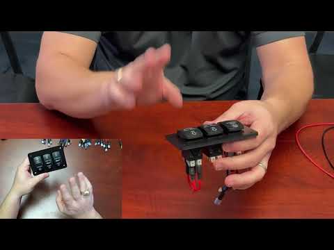
Video reference: confirm the molded terminal numbers on your switch before making a connection.
Step 2
Connect the protected positive feed to terminal 2 and the negative feed to terminal 5. These two feeds are crossed through the switch so the actuator receives opposite polarity in the two momentary positions.
Step 3
Follow the electric trim tab diagram for the cross-jumpers between terminals 1 through 6. The jumper pattern is what reverses the actuator direction. Do not copy the hydraulic switch wiring.
Step 4
Land the actuator wires on the paired motor-output terminals shown in the diagram. Repeat the same pattern on the second switch for the other tab.
Electric wiring diagram
The diagram shows both rocker switches, the polarity-reversing jumpers, and the optional lamp connections at terminals 7 and 8.
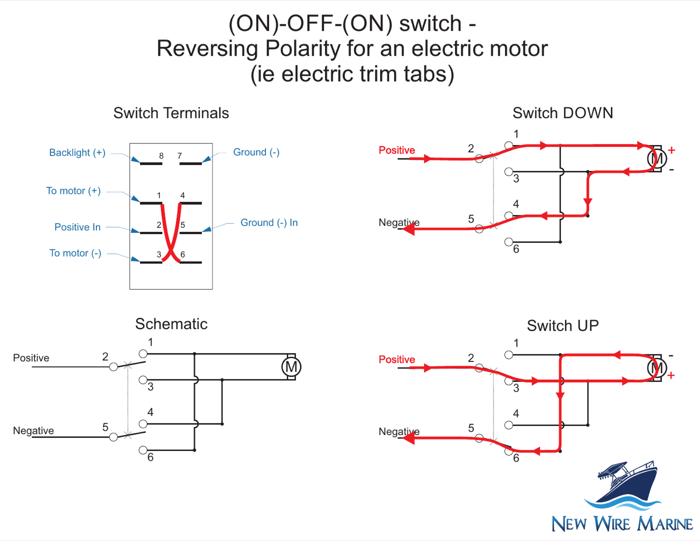
Electric reverse-polarity wiring. Page 1 of the New Wire Marine trim tab diagram.
Different system? Continue with hydraulic trim tabs ↓
Use this chapter if the boat has a hydraulic power unit. The two switches share the pump circuits, while separate valve wires select the port or starboard tab.
Hydraulic trim tabs
This video shows how the two switches share the pump circuits while each switch controls the valve for its side of the boat.
Use this section only if the boat has a hydraulic power unit.
Step 1
Locate the hydraulic power-unit wires and keep the port and starboard valve leads identified. On Bennett color-coded systems, the New Wire Marine diagram labels the pump pressure, pump retract, port valve, and starboard valve circuits.
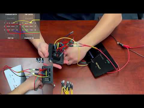
Video reference: the pump circuits are shared, while the valve connection determines which tab moves.
Step 2
Connect protected positive power to terminal 2 and jumper terminal 2 to terminal 5 on each switch, following the hydraulic diagram.
Step 3
The pump-pressure and pump-retract wires connect to the same numbered terminals on both switches. This lets either rocker command the pump in the required direction.
Step 4
Connect the port valve circuit to the switch that operates the port tab and the starboard valve circuit to the switch that operates the starboard tab. The valve connection is what selects the side that moves.
Hydraulic wiring diagram
The diagram shows the Bennett color code, shared pump connections, side-specific valve connections, and optional lamp terminals.
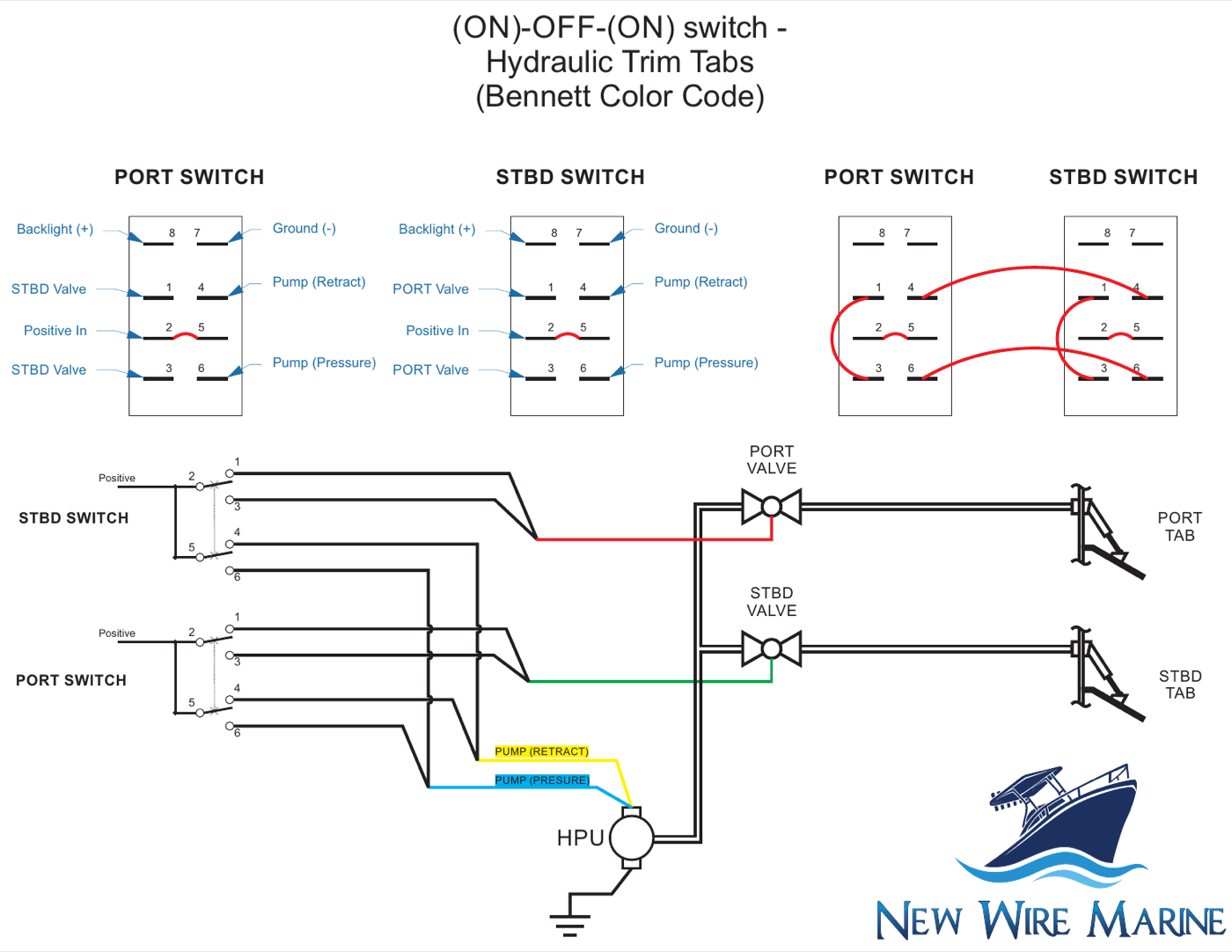
Hydraulic pump-and-valve wiring. Page 2 of the New Wire Marine trim tab diagram.
Test before leaving the dock
Disconnect power and compare the actuator or pump-direction connections with the correct diagram. Do not move wires while the circuit is energized.
On a hydraulic system, check the port and starboard valve connections. On an electric system, check that each actuator pair goes to the intended rocker.
Save a copy of the diagram that matches the installed system and label the wires while the connections are still easy to identify. The next repair will be much quicker.
Products for this project
Match the switch body and terminals to the diagram and to the wiring already installed in the boat.
Confirm the switch function, terminal count, circuit protection, wire size, and connector size before ordering or moving a connection.
Electric tabs have an electric actuator at each tab. Hydraulic tabs use hoses from the actuators to a hydraulic power unit inside the boat. Identify the system before choosing a switch diagram.
The wiring shown here uses momentary (ON)-OFF-(ON) rocker switches. The rocker returns to the center OFF position when you release it.
The crossed connections reverse the polarity sent to the actuator motor. Reversing polarity changes the motor direction so the actuator can extend or retract.
The pump supplies pressure or retract flow, while the valve selects which side receives it. Each rocker therefore controls a shared pump circuit and one side-specific valve circuit.
No. Wire colors can vary, especially after repairs. Trace and label each circuit, then use the switch terminal numbers and the diagram for the system installed on your boat.
Trim tab controls are labeled for the effect on the boat, not simply for the tab on the same side. Test the finished system carefully and follow the trim tab manufacturer’s operating instructions.